US (2.2-5.5кВт 2P)

Vortex Waaier US (2.2-5.5кВт 2P)

Solidpump US-serie pomp is een multifunctionele pomp met een vortexwaaier. De waaier die voornamelijk wordt gebruikt in Volute pompen. Vortex-waaiers genereren een krachtige wervelstroming die het water vanaf de inlaat naar de persaansluiting slingert, waardoor interne verstopping door vastebestandsdelen en vezelachtige stoffen wordt voorkomen.
Toepassing

  • Voor afvalwaterlozing van industriële ondernemingen, winkelcentra, ziekenhuizen, hotels
  • Voor huishoudelijk afvalwater en regenwaterafvoer van afgelegen gebieden, parkeerplaatsen en gemeentelijke voorzieningen
  • Voor het verpompen van afvalwater naar rioolwaterzuiveringsinstallaties
  • Voor het verpompen van water bij landbouw- en aquacultuurfaciliteiten


Technische specificaties

  • Isolatieklasse: B (F op aanvraag)
  • Beschermingsklasse: IP68
  • Water temperatuur: up to 40°C
  • PH: 6 to 10
  • Vloeistofdichtheid: 1.3g/cm3
  • Voeding: 3-fase 400V ±10%, 50Hz
  • Motor beveiliging: ingebouwd
  • Capaciteit :max 70m3/h
  • Opvoerhoogte : max 23mtr
  • Max. dompeldiepte: 10mtr
  • Kabel lengte : 8mtr

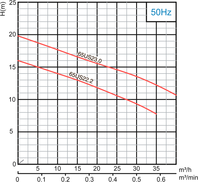
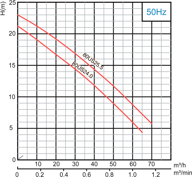
Pomp prestatie curve

Model 50Hz

Voltage

Current

Motor power

Outlet

Rated capacity

Rated head

Max capacity

Max Head

Impeller Passage

Cable


V

A

kW

HP

in

mm

m3 /h

m

m3 /h

m

mm

mm 2

65US22.2

380

5

2.2

3

35

25

10

35

16

56

4G 1.0

65US23.0

380

6.5

3

4

65

25

15

40

20

56

4G1.5

80US24.0

380

8.9

4

5.5

3

80

40

12

65

21

56

4G1.5

80US25.5

380

11.7

5.5

7.5

3

80

50

12

70

23

56

4G2.5

Scroll

Model 50Hz

Voltage

Current

Motor power

Outlet

Rated capacity

Rated head

Max capacity

Max Head

Impeller Passage

Cable


V

A

kW

HP

in

mm

m3 /h

m

m3 /h

m

mm

mm 2

65US22.2

380

5

2.2

3

35

25

10

35

16

56

4G 1.0

65US23.0

380

6.5

3

4

65

25

15

40

20

56

4G1.5

80US24.0

380

8.9

4

5.5

3

80

40

12

65

21

56

4G1.5

80US25.5

380

11.7

5.5

7.5

3

80

50

12

70

23

56

4G2.5

Materiaal van de constructie

Item No.

Part name

Material

01

Hose coupling

Cast iron

01a

Hose coupling

Cast iron

03

Terminal box

Cast iron

05

Upper cover

Cast iron

06

Up-Bearing house

Cast iron

07

Bearing house

Cast iron

10

Seal bracket

Cast iron

11

Motor body

Cast iron

13

Pump body

Cast iron

14

Impeller

Cast iron

17

Coupling adapter

Cast iron

22a

Coupling seat

Cast iron

22b

Upper guide support

Cast iron

27

Stator


28

Rotor

Shaft : AISl304SS

30

Flange

Cast iron

31a

Bearing

Ball bearing

31b

Bearing

Ball bearing

33

Motor protector


34

Mechanical seal

Sio-Ceramic/Can:Jon.Ceramic

35

Oil seal


47

Cable

 
Scroll

Item No.

Part name

Material

01

Hose coupling

Cast iron

01a

Hose coupling

Cast iron

03

Terminal box

Cast iron

05

Upper cover

Cast iron

06

Up-Bearing house

Cast iron

07

Bearing house

Cast iron

10

Seal bracket

Cast iron

11

Motor body

Cast iron

13

Pump body

Cast iron

14

Impeller

Cast iron

17

Coupling adapter

Cast iron

22a

Coupling seat

Cast iron

22b

Upper guide support

Cast iron

27

Stator


28

Rotor

Shaft : AISl304SS

30

Flange

Cast iron

31a

Bearing

Ball bearing

31b

Bearing

Ball bearing

33

Motor protector


34

Mechanical seal

Sio-Ceramic/Can:Jon.Ceramic

35

Oil seal


47

Cable


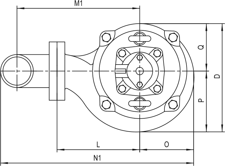
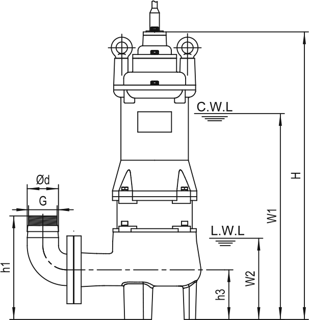
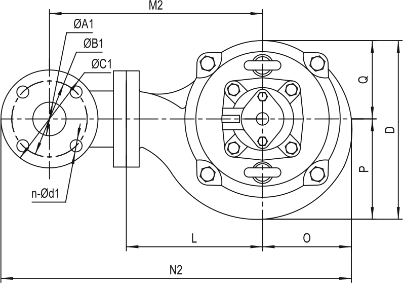
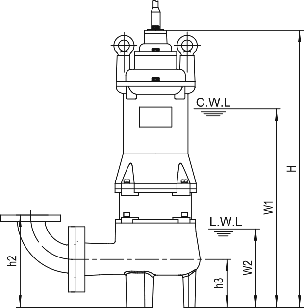
Afmetingen en gewicht

Model

Ød

G

ØA1

ØB1

ØC1

n-Ød1

h1

h2

h3

W1

W2

H

O

P

Q

L

D

M1

M2

N1

N2

65US22.2

65

G2″

65

130

160

4-Ø14

210

210

90

425

170

585

100

102

93

155

195

227

267

360

447

65US23.0

65

G2″

65

130

160

4-Ø14

210

210

90

440

170

620

100

102

93

155

195

227

267

360

447

80US24.0

80

G2½″

80

150

190

4-Ø18

245

240

100

455

170

645

105

110

100

175

210

267

317

410

517

80US25.5

80

G2½″

80

150

190

4-Ø18

245

240

100

480

170

675

110

113

105

175

223

267

317

413

520

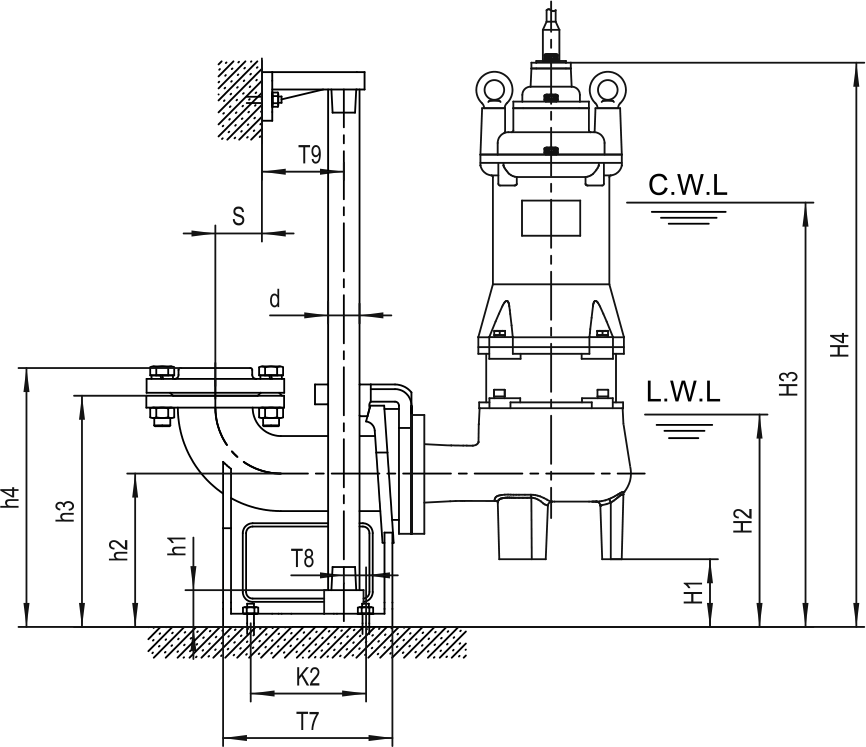
C.W.L: Continuous running water level
L.W.L : Lowest running water level
Scroll

Model

Ød

G

ØA1

ØB1

ØC1

n-Ød1

h1

h2

h3

W1

W2

H

O

P

Q

L

D

M1

M2

N1

N2

65US22.2

65

G2″

65

130

160

4-Ø14

210

210

90

425

170

585

100

102

93

155

195

227

267

360

447

65US23.0

65

G2″

65

130

160

4-Ø14

210

210

90

440

170

620

100

102

93

155

195

227

267

360

447

80US24.0

80

G2½″

80

150

190

4-Ø18

245

240

100

455

170

645

105

110

100

175

210

267

317

410

517

80US25.5

80

G2½″

80

150

190

4-Ø18

245

240

100

480

170

675

110

113

105

175

223

267

317

413

520

C.W.L: Continuous running water level
L.W.L : Lowest running water level

Movable Soft Pipe Installation (R)

Model

R

Y


N.W

G.W

Packing dimension

N.W

G.W

Packing dimension


kg

kg

mm

kg

kg

mm

65US22.2

39

45

700х230х305

43

49

700х230х315

65US23.0

48

54

700х230х305

52

58

700х230х315

Scroll

Model

R

Y


N.W

G.W

Packing dimension

N.W

G.W

Packing dimension


kg

kg

mm

kg

kg

mm

65US22.2

39

45

700х230х305

43

49

700х230х315

65US23.0

48

54

700х230х305

52

58

700х230х315

Movable Hard Pipe Installation (Y)

Model

R

Y


N.W

G.W

Packing dimension

N.W

G.W

Packing dimension


kg

kg

mm

kg

kg

mm

80US24.0

59

64

760х250х335

63

68

760х250х355

80US25.5

73

77

790х260х335

77

81

790х260х355

Scroll

Model

R

Y


N.W

G.W

Packing dimension

N.W

G.W

Packing dimension


kg

kg

mm

kg

kg

mm

80US24.0

59

64

760х250х335

63

68

760х250х355

80US25.5

73

77

790х260х335

77

81

790х260х355

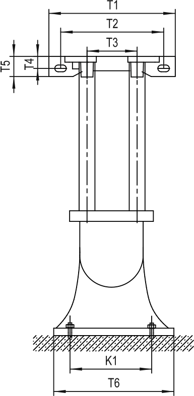
Auto-Coupled Installation (Z)

The coupling and pump will be packed individually, packing dimension and weight in table only refer to the pump, please refer to “Auto-Coupling” page to check coupling's packing dimension and weight.

Auto oupling

ØA

ØB

ØC

N-Ød

T1

T2

T3

T4

T5

T6

T7

T8

T9

K1

K2

S

h1

h2

h3

h4

65-65(PN6)

Ø65 / G2½″

130

160

4-Ø14

280

230

125

30

50

230

235

20

70

190

155

90

25

165

265

295

80-80(PN6)

Ø65 / G3″

150

190

4-Ø18

315

265

145

27

50

255

225

30

78

215

155

70

25

190

305

335

Scroll

The coupling and pump will be packed individually, packing dimension and weight in table only refer to the pump, please refer to “Auto-Coupling” page to check coupling's packing dimension and weight.

Auto oupling

ØA

ØB

ØC

N-Ød

T1

T2

T3

T4

T5

T6

T7

T8

T9

K1

K2

S

h1

h2

h3

h4

65-65(PN6)

Ø65 / G2½″

130

160

4-Ø14

280

230

125

30

50

230

235

20

70

190

155

90

25

165

265

295

80-80(PN6)

Ø65 / G3″

150

190

4-Ø18

315

265

145

27

50

255

225

30

78

215

155

70

25

190

305

335

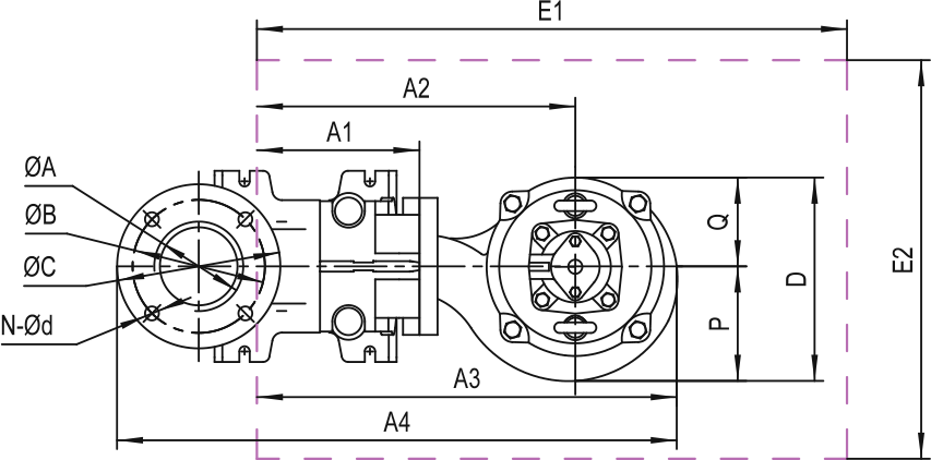
Table size

Model

Auto coupling

H1

H2

H3

H4

A1

A2

A3

A4

P

Q

D

E1xE2

Pump weight & packing dimension


N.W

G.W

Packing dimension

65US22.2

65-65(PN6)

75

245

500

660

155

245

410

580

102

93

195

650x550

36

42

700x230x305

65US23.0

65-65(PN6)

75

245

515

695

155

245

410

580

102

93

195

650x550

46

51

740x230x305

80US24.0

80-80(PN6)

90

260

1180

1680

335

825

1184

1676

398

320

718

650x550

54

59

760x250x335

80US25.5

80-80(PN6)

90

260

570

765

175

260

460

632

113

105

218

650x550

68

71

790x260x335

Scroll

Model

Auto coupling

H1

H2

H3

H4

A1

A2

A3

A4

P

Q

D

E1xE2

Pump weight & packing dimension


N.W

G.W

Packing dimension

65US22.2

65-65(PN6)

75

245

500

660

155

245

410

580

102

93

195

650x550

36

42

700x230x305

65US23.0

65-65(PN6)

75

245

515

695

155

245

410

580

102

93

195

650x550

46

51

740x230x305

80US24.0

80-80(PN6)

90

260

1180

1680

335

825

1184

1676

398

320

718

650x550

54

59

760x250x335

80US25.5

80-80(PN6)

90

260

570

765

175

260

460

632

113

105

218

650x550

68

71

790x260x335

This site uses cookies and related tracking technologies to personalize and enhance your experience on this site. By approving Privacy Policy you consent to the use of your personal data and cookies.